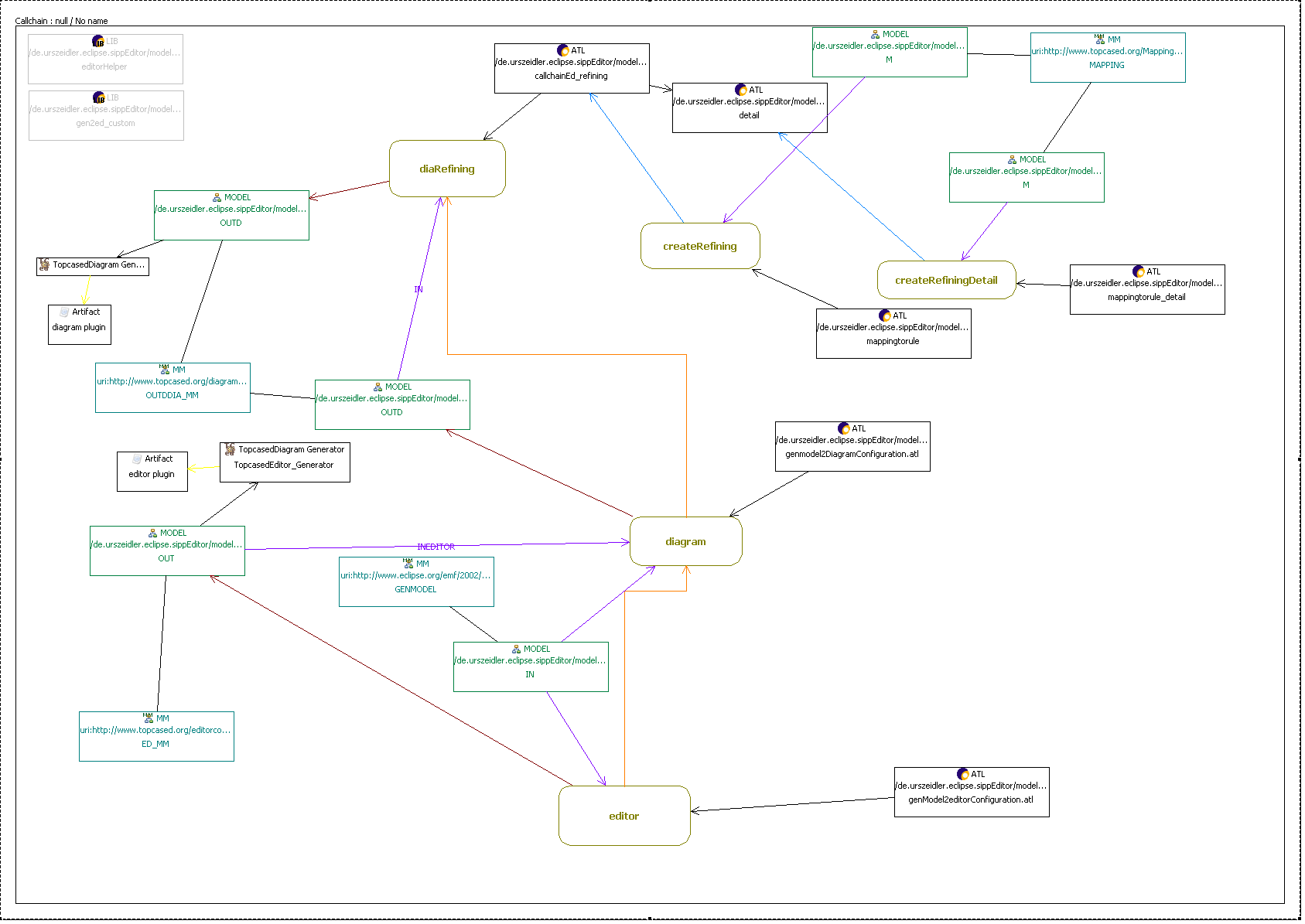
For the generation of a diagram editor with the topcased toolkit, the plug in provide an extra wizard, creating all necessary resources to transform the base model in the diagram and editor model. As the origin model, describes some structure, not all necessary informations for transforming in a diagram editor are provided by the model. For example the graphical representation and the viewpoint of the relation. In the transformation process the destination model will be supplied with the additional information.
In the MDE it is common that your models are changing over the time, so the solution is to transform to all the dependent models, rather than modelling them by hand, because they getting out of sync.
You will need a ready generated ecore model, just like the emf tutorial describes or the topcased dia generation. The wizard need the xxx.genmodel as input. After finishing the wizard, all resources are created in the directory where your genmodel lies. At this state you need the xxx_gen2ed_custom.atl, and define the base informations, by setting the values of the helpers in the atl file. In this file you define the exceptions, "convention over coding". All ecore classes will be transform to nodes, except the ones specified in the helper linknames(). Some comments in the file will describe whats the meaning of the helpers. The main work is describing what model elements are nodes, and what are edges. Also for simple objects, only part of the diagram. After this you need to execute the refining and reining detail transformation. This will create the ATL files to proceed the refining.
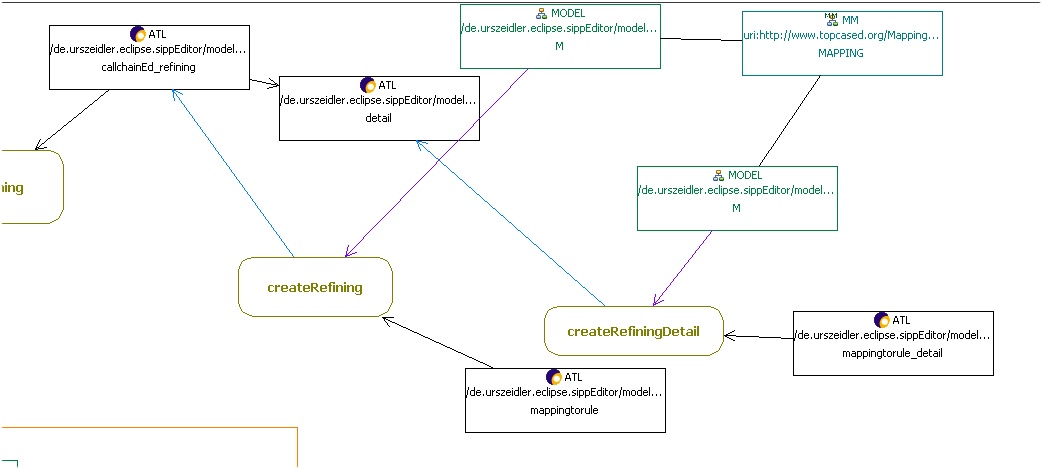
The relations of the model elements are defined by source_target_couple. After creating the ATL files you need to work on the xxx_refining_detail.atl. Be careful with this file because every time you execute the "createRefiningDetail" transformation, this file will be rewritten. The best way is leave it alone. You could rename the file in xxx_refining_detail_working.atl and update the URI property of the detail ATL Res. In this file for each link element is a rule where you can define the source_target_couple. The rule creates a SourceTargetCouple (stc) for each string in objects. As there is only one rule to create several stc the best way is to store the needed discriminator in the string. You could also create an other stc. You set the values with helpers, accessing the base model. Take a look at the file editorHelper.atl in the atlres folder.
Themrule EdgePartConfigurationRule_labelLink_Recv {


    from invar :
OUTDDIA_MM!EdgePartConfiguration
(invar.oclIsTypeOf(OUTDDIA_MM!EdgePartConfiguration)  and
invar.className()= 'labelLink_Recv')


    using {


        objects :
Sequence(String) = Sequence{};


    }    to
EdgePartConfigurationvar : OUTDDIA_MM!EdgePartConfiguration (


presentation <- invar.presentation,


fontChangeable <- invar.fontChangeable,


        lineWidth
<- invar.lineWidth,


        lineStyle
<- invar.lineStyle,


        prefix
<- invar.prefix,


sourceDecoration <- invar.sourceDecoration,


targetDecoration <- invar.targetDecoration,


defaultRouter <- invar.defaultRouter,


        object
<- invar.object,


constraint <- invar.constraint,


sourceTargetCouple <- SourceTargetCouplevar,


edgeObjects <- EdgeObjectsvar,


directEditable <- EdgeObjectsvar.first()


     ),


    SourceTargetCouplevar : distinct
OUTDDIA_MM!SourceTargetCouple foreach(o in objects)  (


        --
containerType <-
#SOURCE,#NONE,#DIAGRAM,#SOURCE_CONTAINER,#TARGET,#TARGET_CONTAINER,


        --
autoRef <- false,


        --
reversible <- false,


        --
containerObject <- thisModule.getObject(o).genClass,


        --
sourceNode <-  thisModule.getNodeOUT('RefType'),


        --
targetNode <-  thisModule.getNodeOUT('RefType'),


        --
containerRef <- thisModule.getObject('RefType').genClass,


        --
refSourceToTarget <-
thisModule.getFeatureFromName('RefType','bean') ,


        --
refTargetToSource <-
thisModule.getFeatureFromName('RefType','bean') ,


        --
refEdgeToTarget <-
thisModule.getFeatureFromName('RefType','bean') ,


        --
refTargetToEdge <-
thisModule.getFeatureFromName('RefType','bean') ,


        --
refEdgeToSource <-
thisModule.getFeatureFromName('RefType','bean') ,


        --
refSourceToEdge <-
thisModule.getFeatureFromName('RefType','bean')


     ),


    EdgeObjectsvar : distinct
OUTDDIA_MM!EdgeObject foreach(o in objects)  (


        -- id
<- 'label_'+ invar.className(),


        -- type
<- #Middle,


        --
eStructuralFeature <-
thisModule.getFeatureFromName('Transition','condition')


     )


do {


 invar.debug('EdgePartConfigurationRule_labelLink_Recv');


 }


 }
After you have define your relations you are ready to execute the transformation via context menu. Starting at editor will create both models.